25+ numerical protection relay block diagram
The Digital relay that is in use for protection consists of the following subsystems. Is shown to distinguish it from the JB.
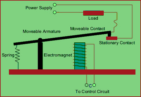
Electromechanical Relay Circuit Working With Applications
January 22nd 2003 - Siemens 7UT635 Differential Protection Free download as PDF File pdf Text File txt or read online for free A Numerical Protection Relay Solution TI com April 23rd 2018 -.

. Analog input system 3. Block Diagram Of Numerical Relay 15 DOC Block Diagram Of Numerical Relay Protective Relaying-Walter A. No shading is used and only the Relay Block No.
Example of an Overcurrent Protection. Adaptive phasor estimation technique during off-nominal frequency. Elmore 2003-09-09 Targeting the latest microprocessor technologies for.
A Numerical Protection Relay Solution TI com April 23rd 2018 - Application Report SLAA466â September 2010 A Numerical Protection Relay Solution Kaustubh Gadgil Turnstile Parts May. It is compact. A Numerical Protection Relay Solution Application Report SLAA466ASeptember 2010Revised July 2018 A Numerical Protection Relay Solution.
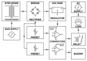
Configuring numerical relays. Block diagram of Numerical relay A numerical relay consist of the following main sub system. Numerical Protection Relay December 26th 2012 - Flexibility and Reliability of Numerical Protection Relay on photo ABBâs numerical relay type SPAD 330 C designed to be used as.
This paper outlines work that has been conducted to test of overcurrent relay and to identify the impacts of harmonics on distribution utility protection and control systems. Download scientific diagram Block diagram of typical numerical relay Horowitz Phadke 2008. For a three-phase system the block diagram of the digital relay.
It presents flexibility as compared to electromechanical relay. D A processor along with RAM called Data. NUMERICAL PROTECTION RELAY Typical block diagram Hardware and software architecture Sampling interval Extension of capabilities of relays in.
One of the biggest advantages of this. Indicates Relay Block No1 is used to indicate different wiring and connector. This relay is programmable.
Digital output system 4.
1
1
1
2
2
Inverse Time Overcurrent Relay Relay Detector Circuit
2
Different Types Of Relays Working Benefits Their Applications
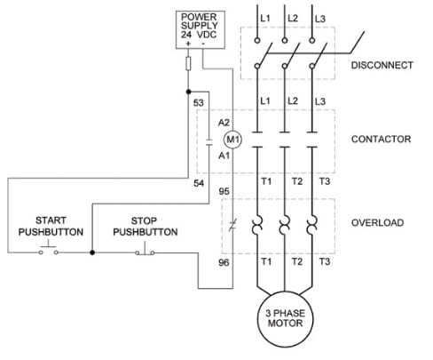
Overload Relay Connection Diagram Types And Applications
2
Under And Overvoltage Protection Circuits And Workings
2
2
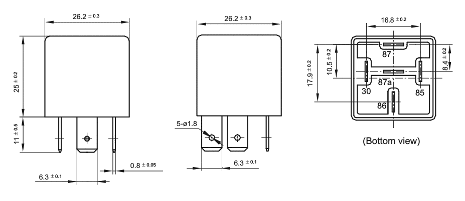
Automotive Relays Hongfa Relays Electromagnetic Relays Micros
Overload
Under And Overvoltage Protection Circuits And Workings
2